Yūbinkyoku 🏣
Tristan Hume's photorealistic path tracer made for CS488
Made as my final project for UWaterloo's CS488 Graphics class, this is the demo page for my path tracing renderer made with the goal of maximum photorealism. I put about a full time month's worth of work effort into this project, way more than required, since I was having a lot of fun and had a final scene in mind I wanted to reach.
It's named after the Japanese word for "post office" because it made so little sense as the name for a ray tracer that it made me burst out laughing, and the fact that there's an emoji for it sealed the deal. Why the idea of naming it after the Japanese word for "post office" occurred to me in the first place is a long story.
It's not open source since it uses some code (e.g OBJ file loading) from the course, and there are better open source renderers out there. But if you want more technical details you can read the project report, although it's written with an intended audience of the course TAs.
Prologue
First, for context for the rest of the renders, all my renders use an implementation of a subset of the Disney BRDF (Burley 2012). This is a high quality physically based microfacet BRDF including proper Fresnel and other effects for dielectrics and metals. My implementation has three parameters: base colour, metalness and roughness. I also implemented Phong Shading for my meshes.
After implementing the Disney BRDF, I rendered a simple scene with both Blender’s Cycles renderer and mine and they were a perfect match, which gave me confidence and allowed me to tune materials in Blender.

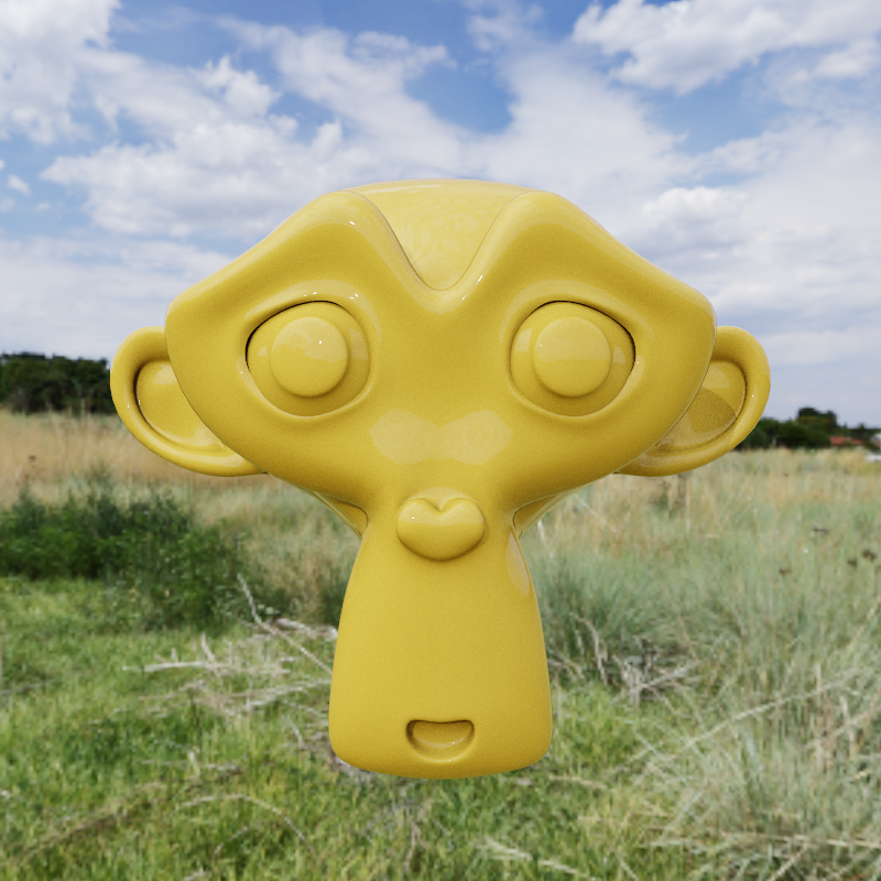
Disney BRDF
Suzanne monkey head model with dielectric 0.5 roughness Disney BRDF material.
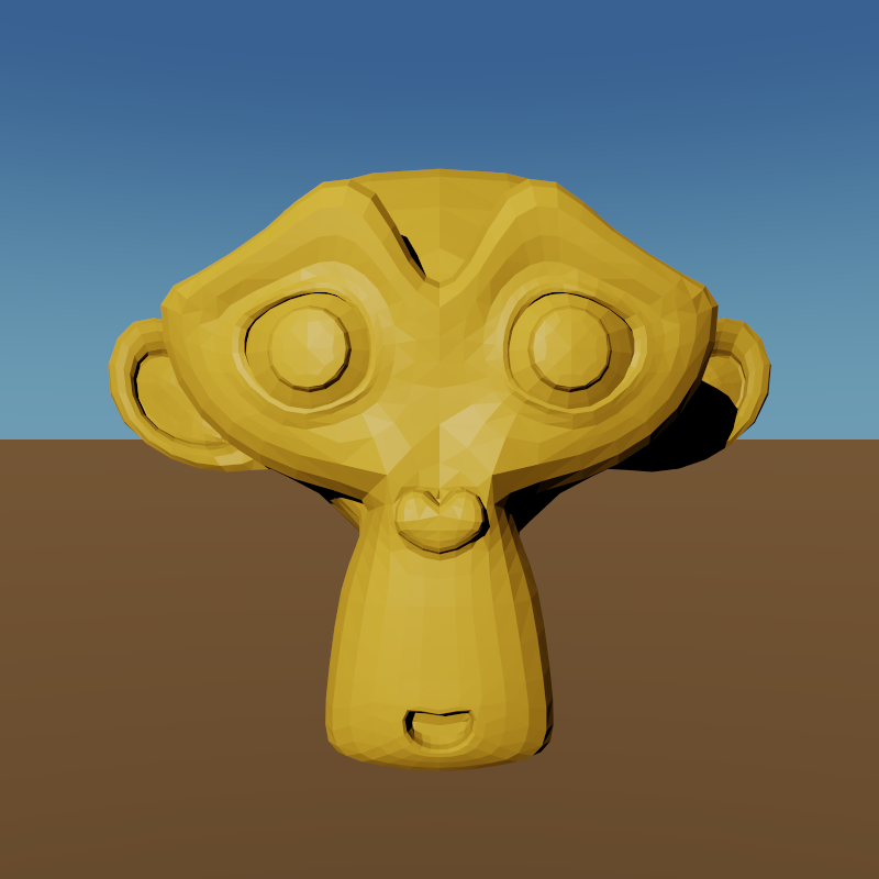
No Phong Shading
Same scene rendered with Phong shading disabled.
Texture Mapping
I implemented texture mapping by making my material take all of its attributes from a texture, and then implented the ability to create constant and image texture files from Lua. I added UV coordinates for meshes, cubes and spheres. Textures are filtered with bilinear filtering of the 4 nearest texels.
This allows mapping base colour, metalness and roughness. I also added special support for emission textures and rendering inside spheres to support environment maps.
Sky emission sphere
Sky texture mapped onto the inside of a giant sphere.
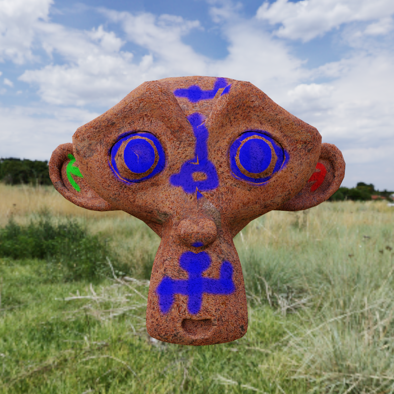
Painted mesh
Texture painted in Blender, also looks glitchy there.
Varying material
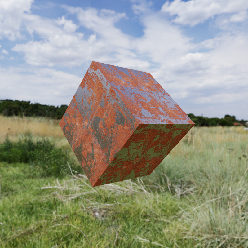
Colour, metallness and roughness textures on a cube.
Normal Mapping
I implemented normal mapping including the required tangents for meshes, cubes and spheres.
I verified with the test texture shown on the cube that the normals have the correct orientation.
Moving highlights
Animation showing moving normal mapped highlights
Test normal map
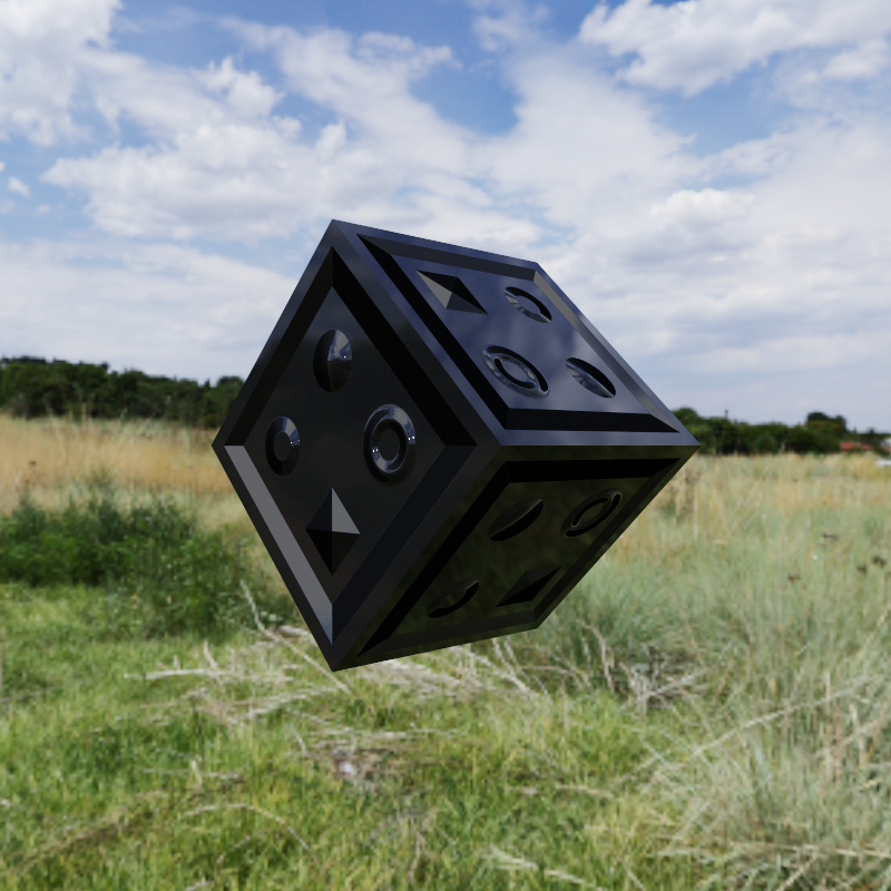
Shiny plastic cube with normal map
Fancy normal map
Textured and normal mapped surfaces
Path Tracing
I implemented global illumination using path tracing. I importance sample both the diffuse and specular lobes of the Disney BRDF.
My integrator is based on the path formulation of the rendering equation, where the integration is done in the outer loop so that path components can be re-used as they are extended and checked against direct lights at each bounce.
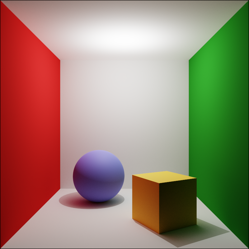
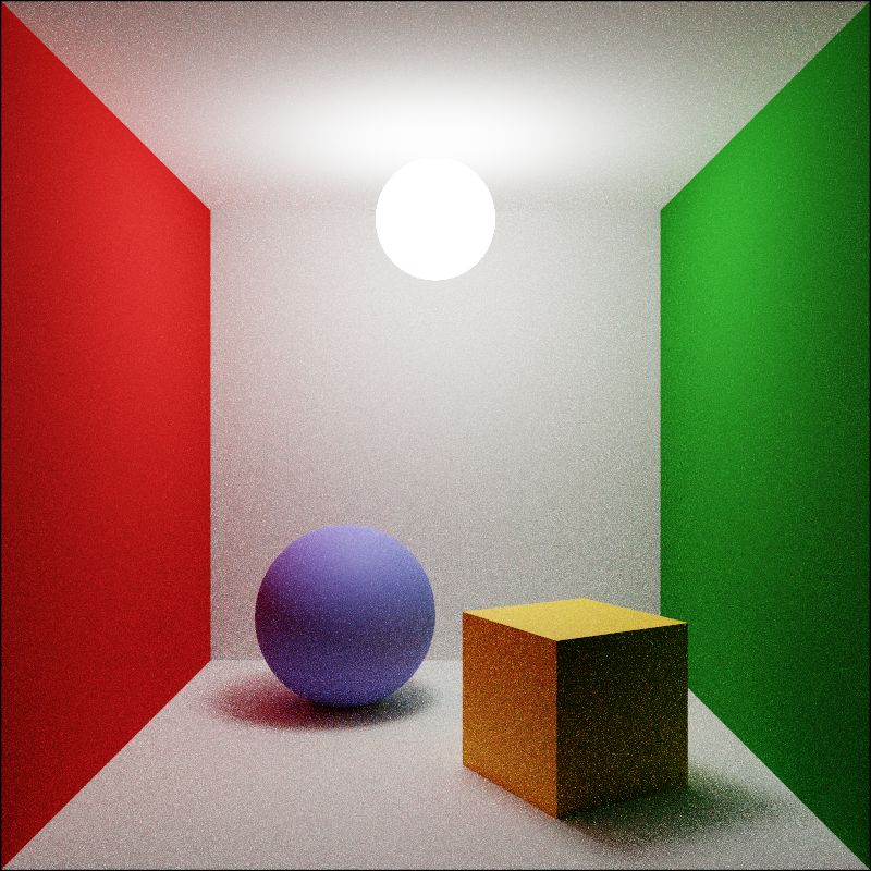
Cornell box
Cornell box with diffuse objects showing colour bleed
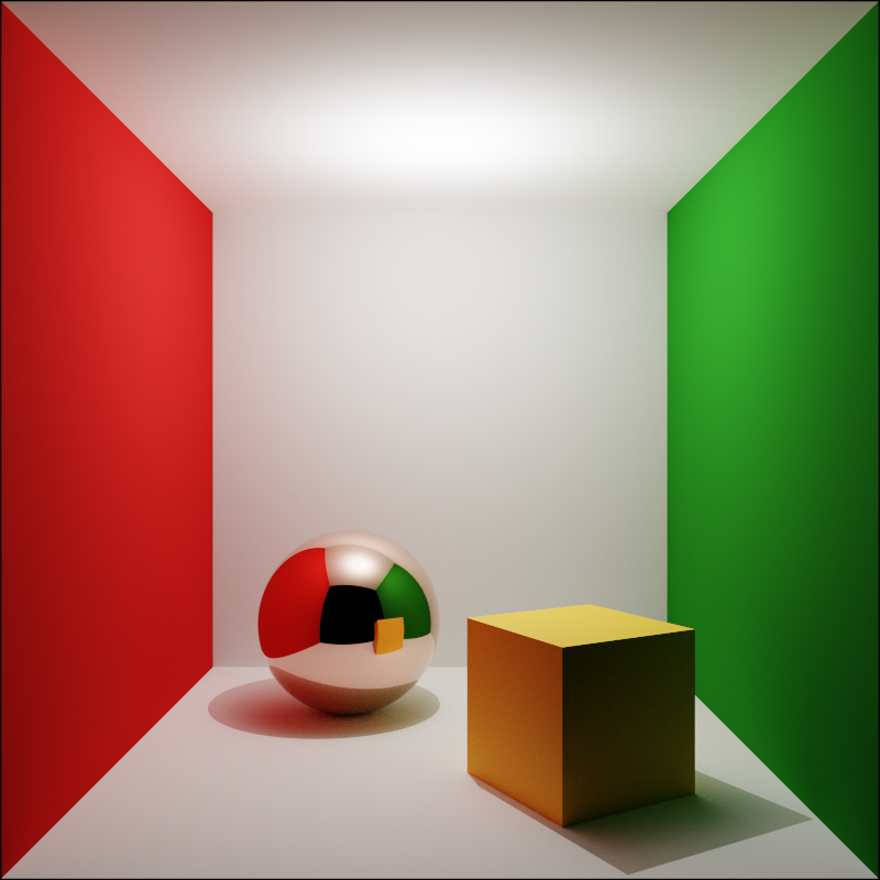
Reflective sphere
With a sphere material emulating polished copper
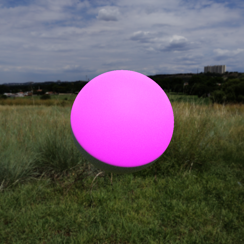
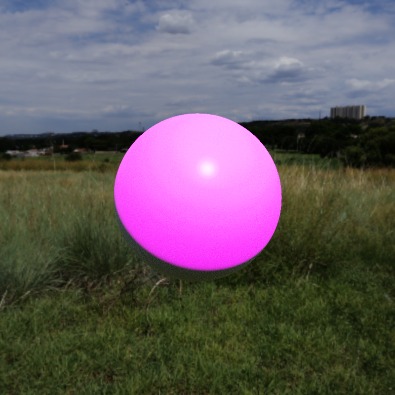
Soft Shadows
I implemented soft shadows by overhauling my lighting model so that lights are just spheres with an emission texture on them, just like environment maps. I then changed the lights array normally passed into the render to just a list of GeometryNodes to sample explicitly.
The path tracing integrator then at each bounce samples the cone of directions subtended by the sphere that would fit in the bounding box of the objects. This means at the moment only spherical area lights work correctly. This is more efficient than sampling a point on the sphere since only visible positions on the light are sampled.
This also allows me to render the area light as a physical object that exists in the world, or I can put it in the list to be sampled but not in the scene for an invisible light.

Soft shadows
Cornell box with area light
Glossy Reflection
Glossy reflection falls out directly from the path tracing integrator and the specular lobe of the Disney BRDF, which uses an empirically based GGX distribution for the microfacet normals. I importance sample the GGX distribution term of the specular lobe so glossy reflection converges quickly.
With path tracing the only difference between specular highlights and glossy reflection is whether the light was directly sampled!
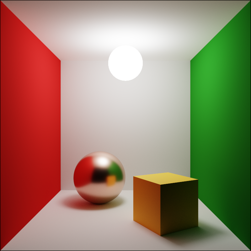
Glossy reflection
Cornell box with rough copper sphere
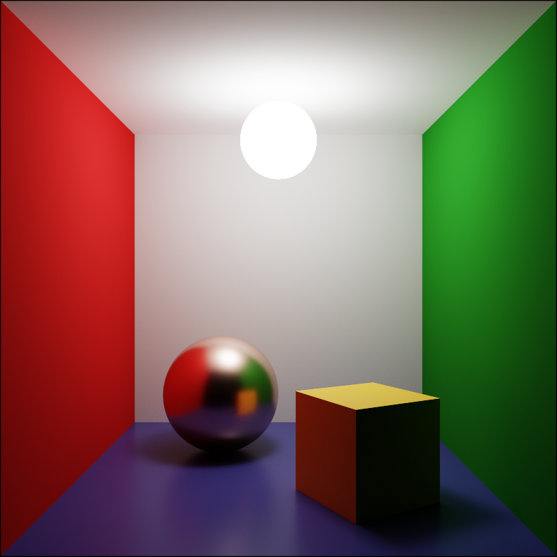
Glossy floor
Cornell box with shiny dielectric floor
Anti-aliasing
Anti-aliasing is implemented as part of the same sampling framework that the path tracing uses. On each sample a random position in a square pixel region is picked to cast the ray for.
For textures I only do bilinear filtering with 4 texels so for high resolution textures anti-aliasing is also necessary for textured surfaces to look correct.
Cube with no AA
Textured cube without anti-aliasing
Cube with AA
Textured cube with anti-aliasing
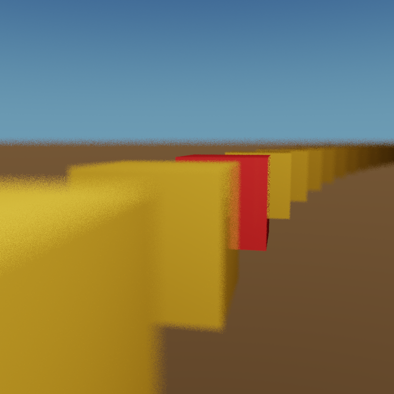
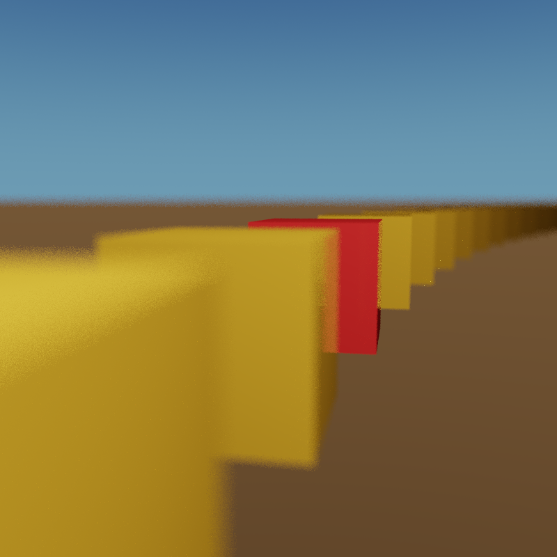
Depth of Field
I implement the thin lens model of depth of field by finding where the original ray intersects the focal plane, then sampling a random point on a disk representing the aperture of the camera and casting a ray from that point to the point on the focal plane.
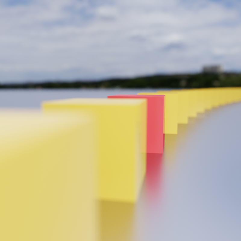
Cubes with DOF
Focal point is on the red cube
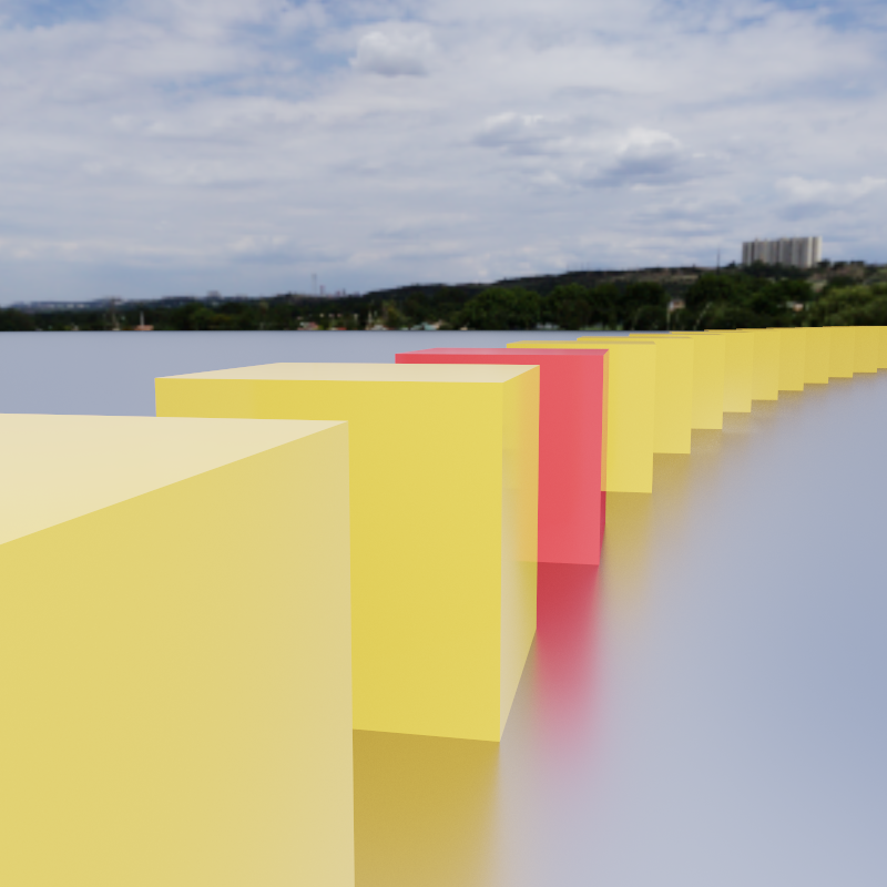
No DOF
Comparison rendered with zero aperture
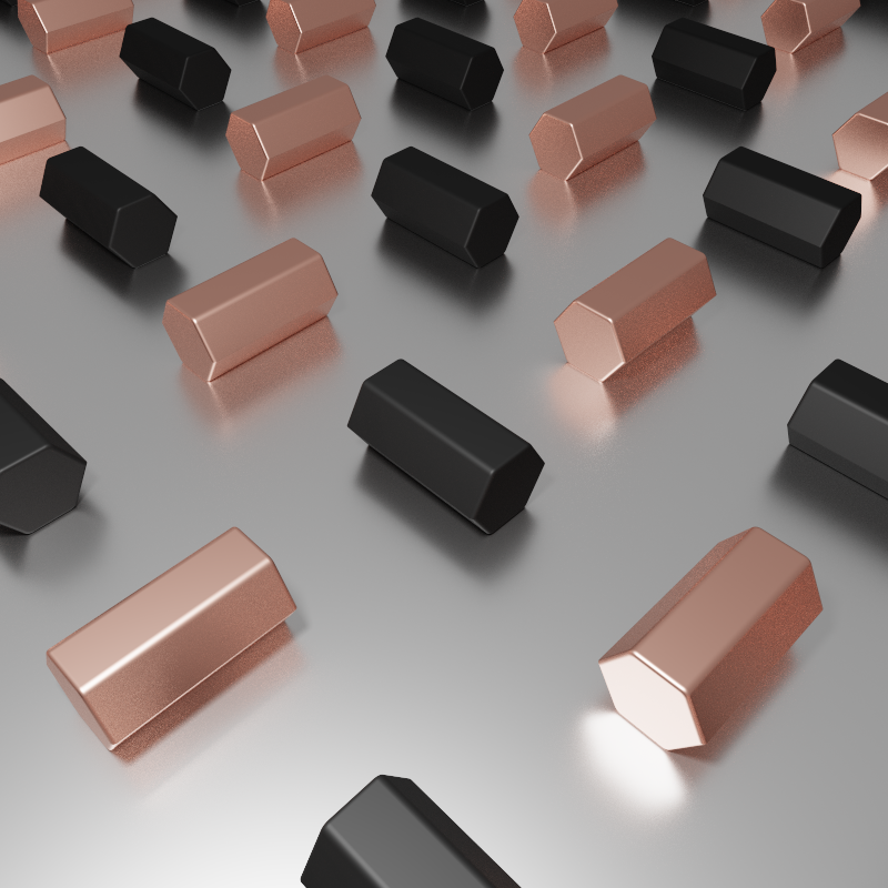
Animation
I implemented animation in Lua by constructing multiple scenes and rendering them to separate files, then using FFMPEG to stitch them together. The animation is done with math, logic and a cosine-based curve for smoothly easing in and out.
This scene shows a perfectly looping animation with rose gold and black plastic rounded hexagons on a metal surface. It was heavily inspired by this animation.
This also shows off a bit of the distance field ray marching explained in the next section. In this case I use modulo to do a domain repetition of a rounded hexagonal bar primitive formula with the parameter being the rotation, which is driven from Lua.
Abstract animation
Perfect loop!
First frame
Uncompressed render
Constructive Solid Geometry
I implemented Constructive Solid Geometry (CSG) in a different way than is standard for ray tracers. I implemented a primitive for ray marching a distance field. This is a method of rendering a 3D surface given a function from a point to the distance to a surface by taking steps along a ray based on the function.
Once that is implemented, CSG is simple to implement by taking the minimum (union) or maximum (intersection) of two distance functions, subtraction is taking the maximum with the negative of a signed distance function.
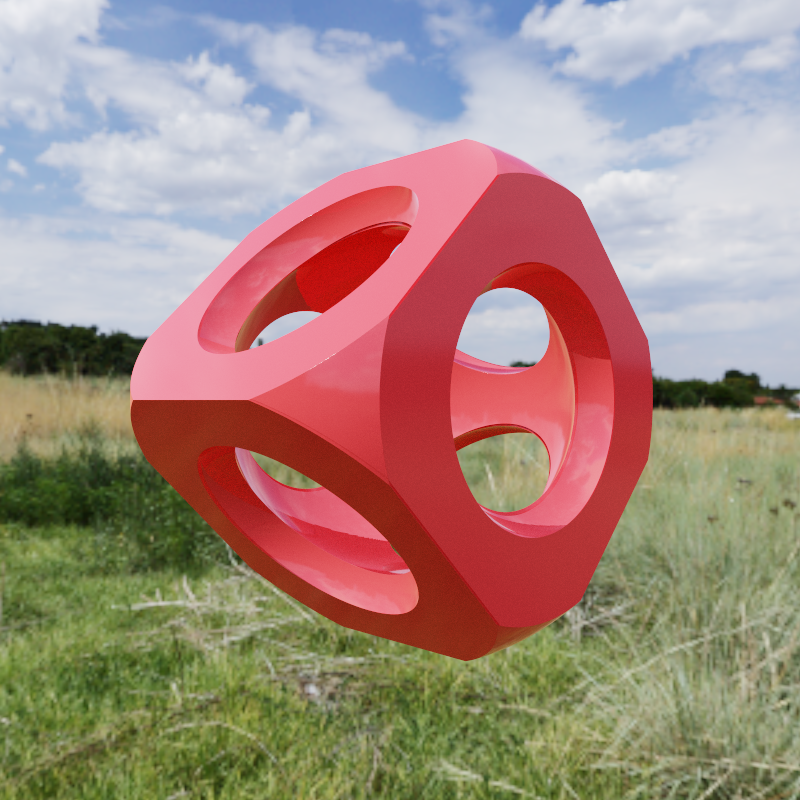
CSG Shape
Cube with spheres and ellipsoids subtracted and intersected
CSG Animation
Showing parameterization and that it’s not a mesh
Mandelbox Primitive
Using distance field ray marching it is possible to render Mandelbrot-style iteration fractals by using the running derivative of the iteration as a distance estimate. I implemented the distance function for one such fractal, the Mandelbox.
I then used CSG to subtract and intersect with some cubes to carve out an interesting region inside the fractal, since the outside isn’t too impressive.
Small Mandelbox
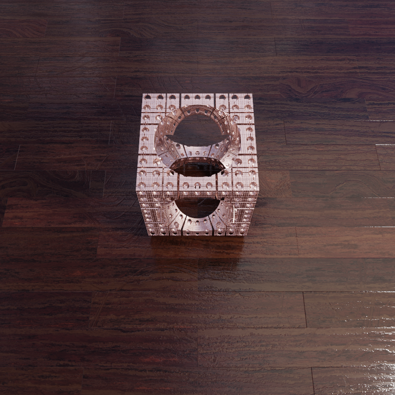
Wooden floor and small copper Mandelbox
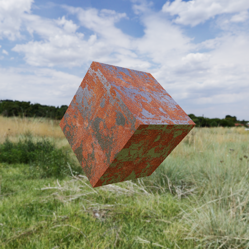
Big red Mandelbox
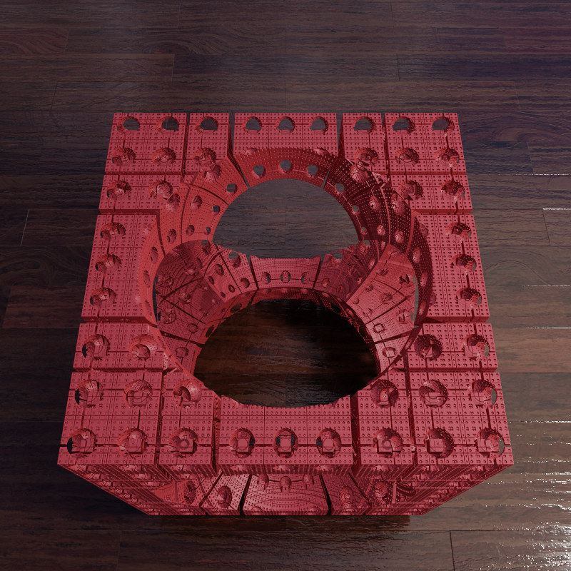
Wooden floor and big red Mandelbox
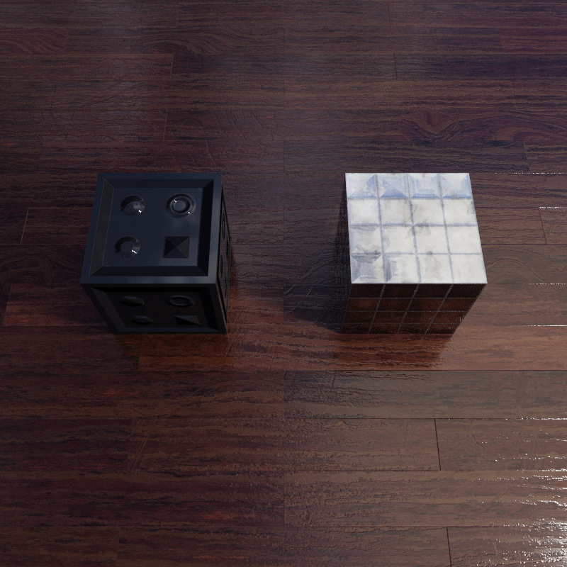
PORTALS!
In order to implement my final scene concept I needed portals, which for my case meant a way to have an object act as a portal where rays passing through it would end up in a different scene, bidirectionally.
I implemented this by giving all rays and surface hits a world number field. Then I modified my code so all scattering and light sampling would observe the world field and cast follow up and shadow rays with the same world.
Then I added a portal SceneNode subclass that checks the world ID of incoming rays and first tests it against that index of its children, as well as a special portal node pointer, and if it hits the portal before it hits the current world, it spawns a new ray in the next world number modulo its number of children, and does the required changing and remapping ray t values to spawn the new ray at the portal.
Portal
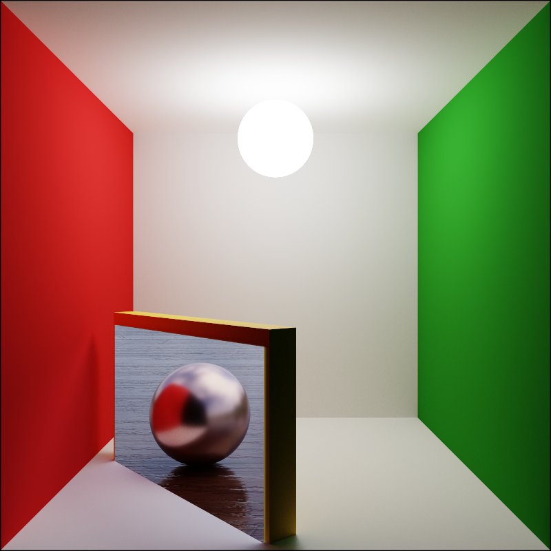
Portal from Cornell box to wooden floor scene
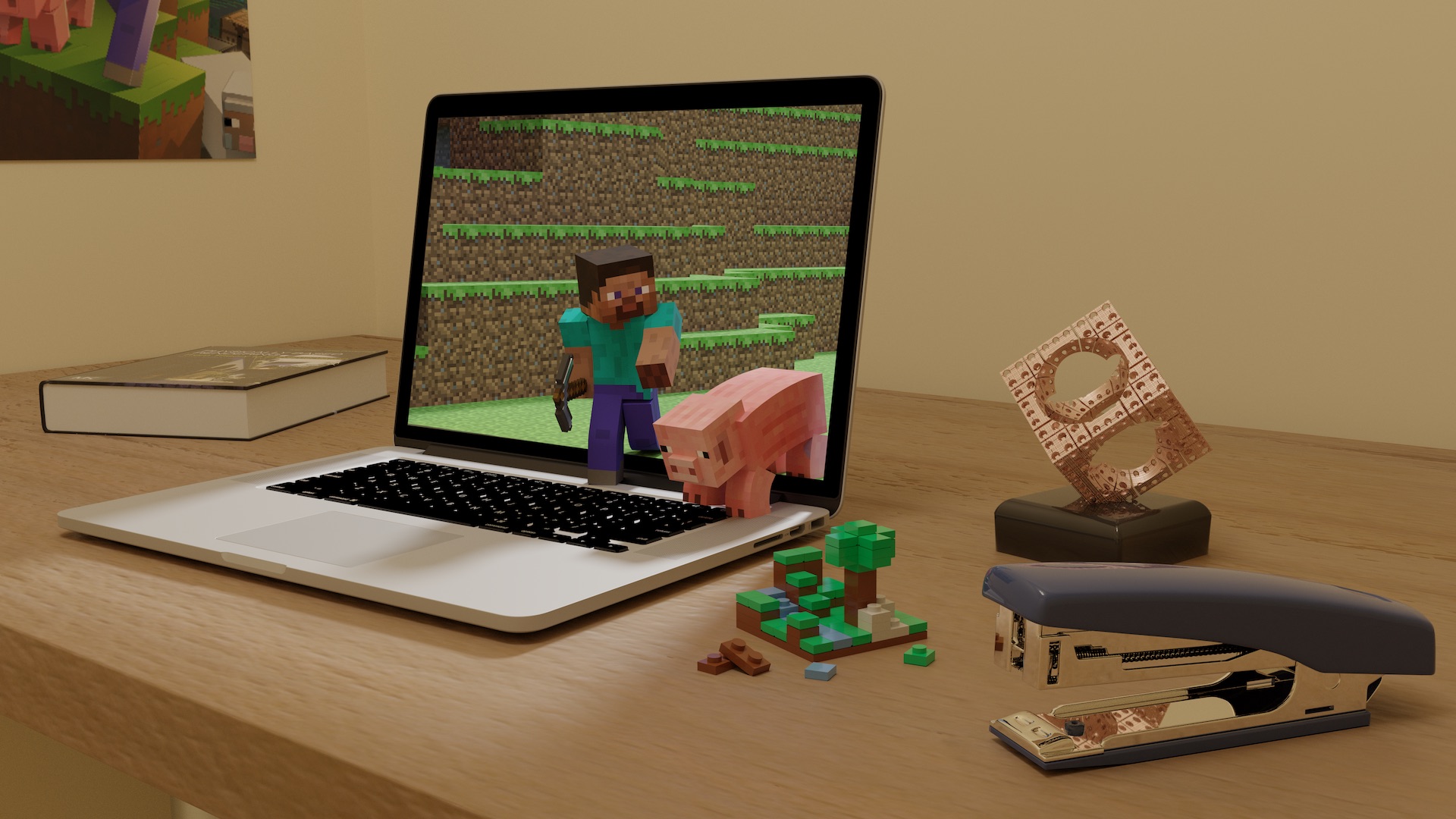
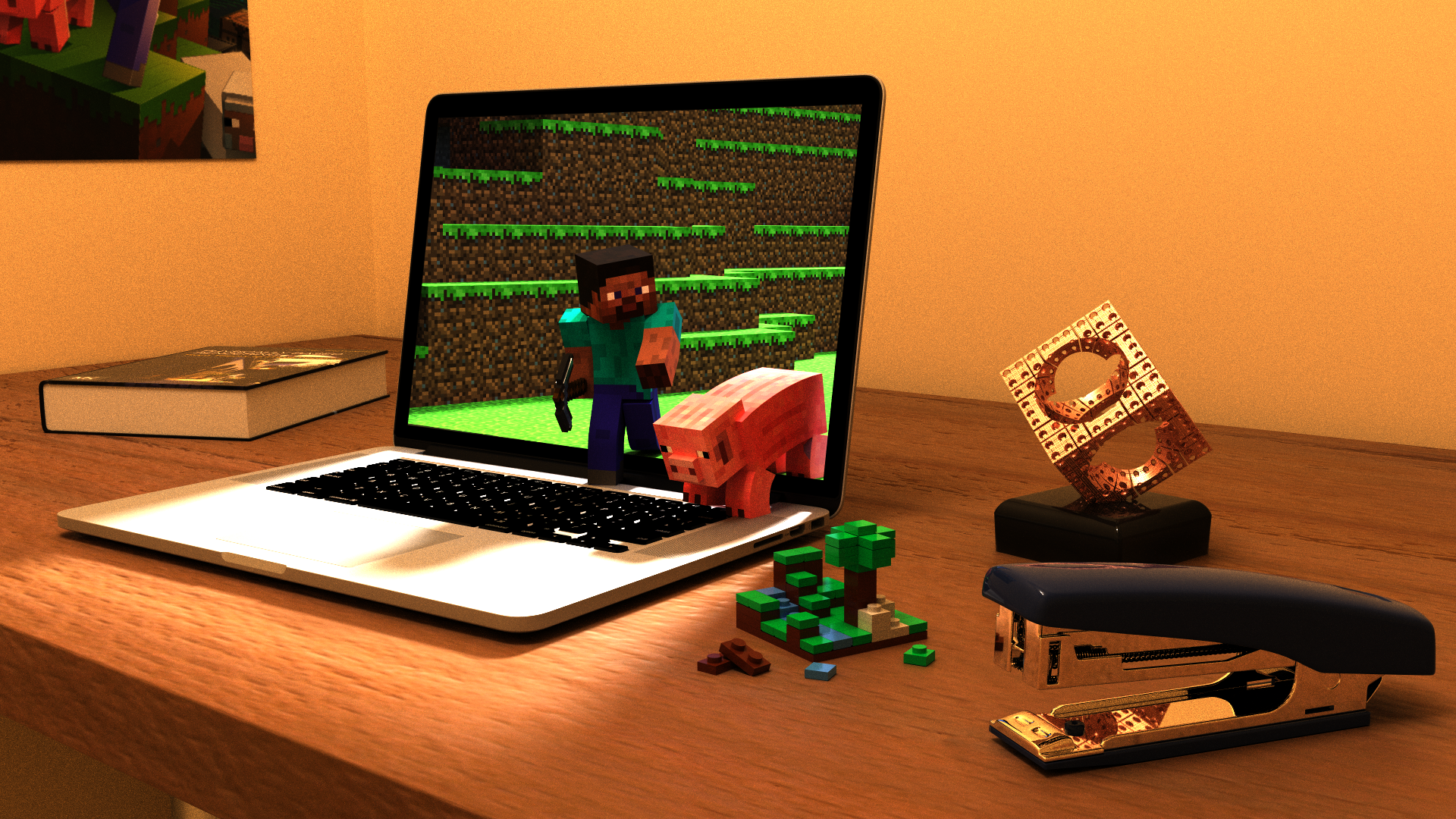
Final Scene: "Realism"
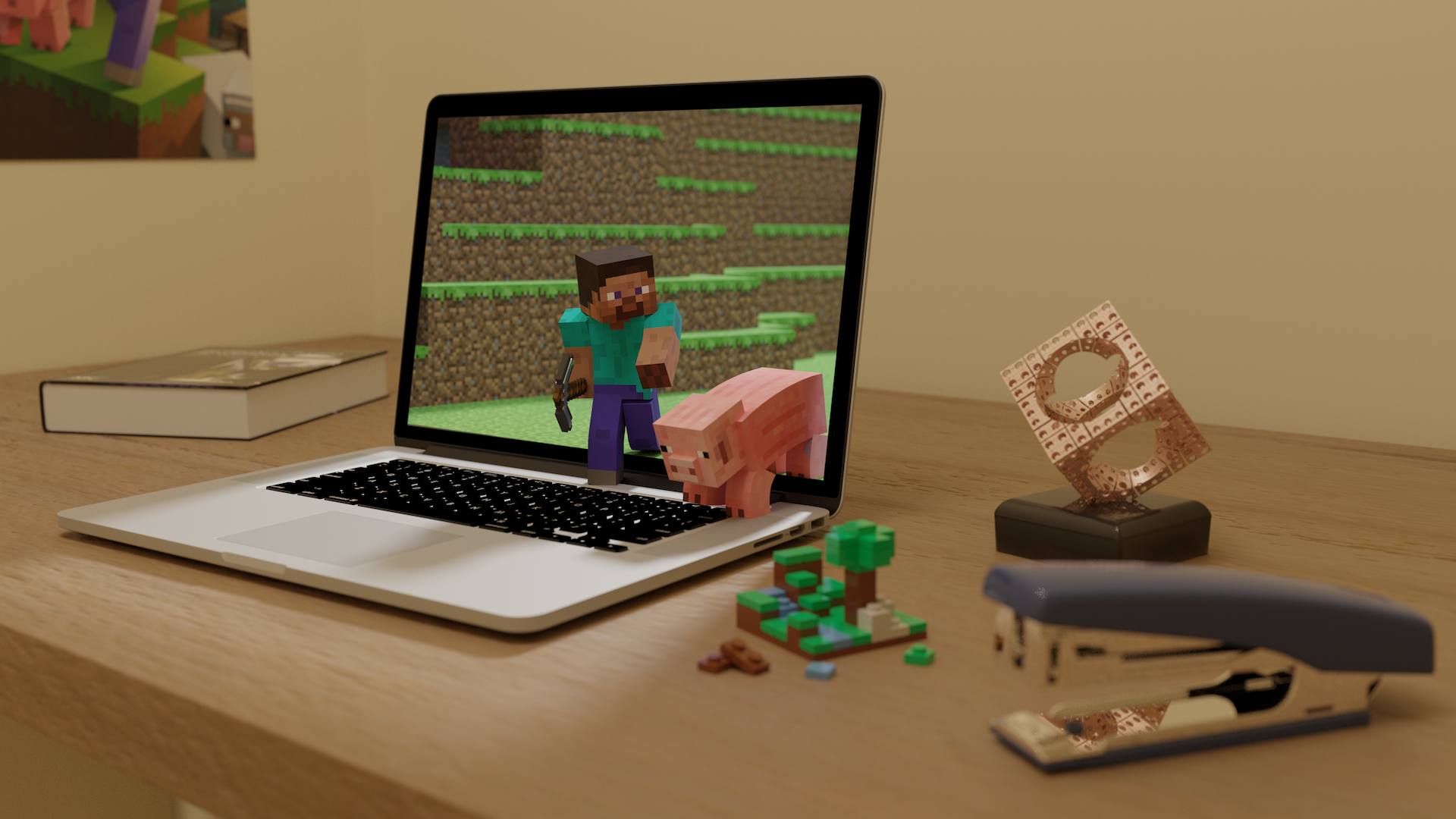
My goal was to render a scene that was as photorealistic as possible while having whimsical elements that clearly couldn’t be real. The scene shows off high quality textures and models (not done by me) in a scene I arranged and tuned the materials for. I also tried to compose an artistically nice scene that tells a story. Uses a portal, a Mandelbox, global illumination, and various hand-tuned Disney BRDF materials.
While I didn’t make most of the models and textures, I still spent over 15 hours arranging, tuning materials and light, composing the scene, and importing various model formats.
Extras shown: Non-filtered textures

Final Scene
My best scene
With depth of field
With artistic DOF
Filmic Tone Mapping
An important part of the photorealism of my renders is very high quality tone mapping. I implemented a parser for the 1D and 3D OpenColorIO lookup table (LUT) formats, and a function to apply them correctly with linear and trilinear interpolation respectively.
The good tone mapping allows for scenes with realistic high dynamic range lighting to render properly without getting blown out and with photo-like colour. As you can see from the render with no tone mapping where the colours are bad, the sun on the keyboard is totally blown out, and the shades of black on the display rim are lost.
I can also use different LUTs for different scenes. I rendered my final scene with a more camera-like LUT with lots of dynamic range, but the rest of my scenes with a higher contrast LUT that gives punchier colours but isn’t as photorealistic.
I can also use a false colour LUT to see what the dynamic range of my scene is like.
No mapping
Final scene with no tone mapping
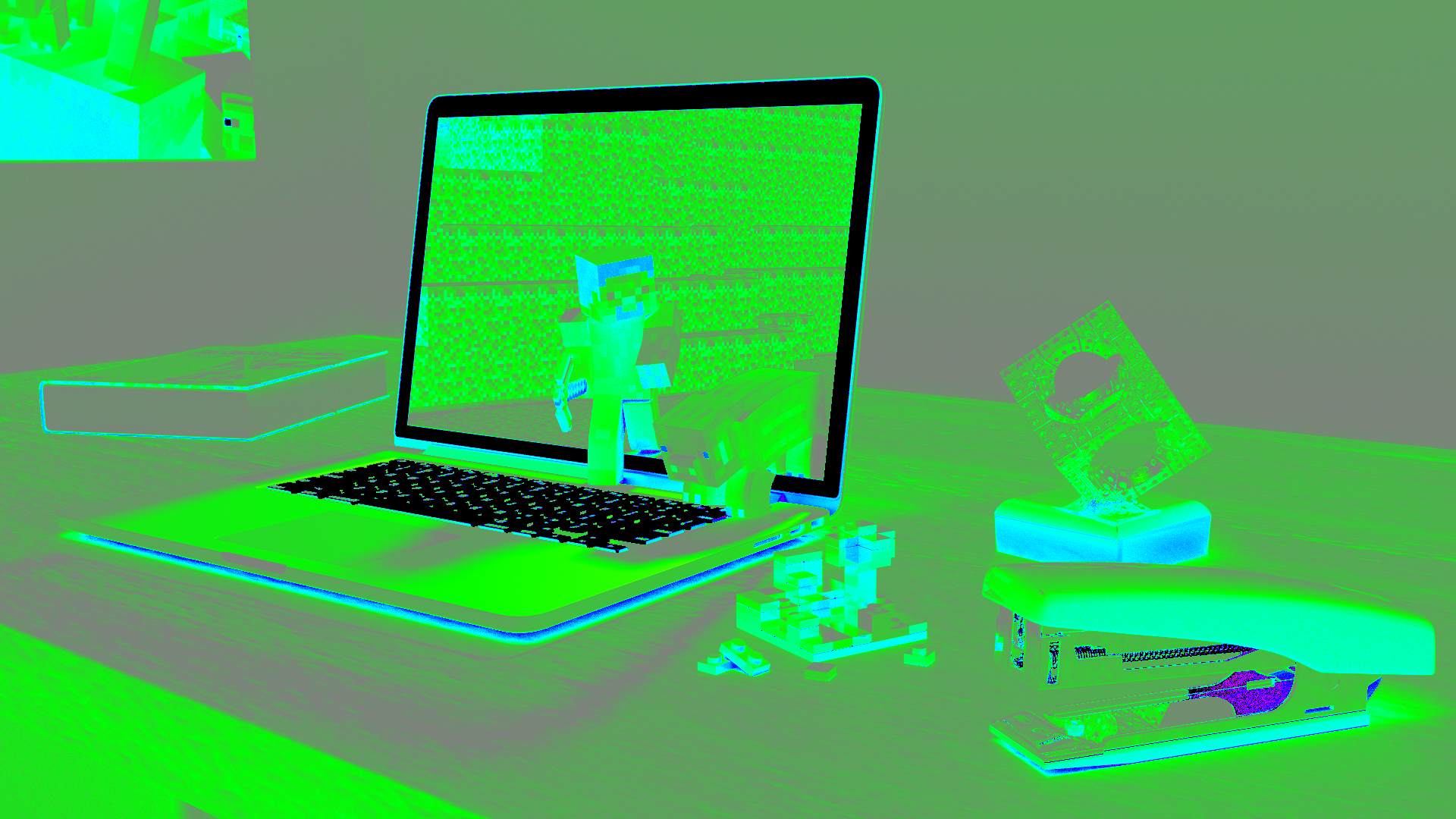
False Colour
Showing dynamic range
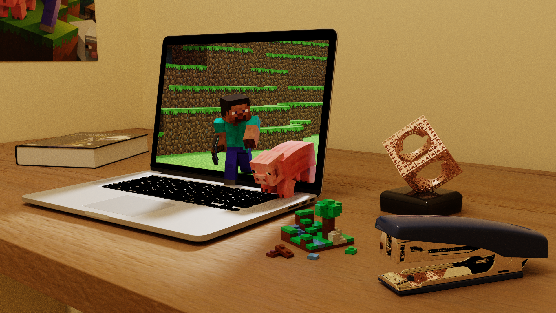
Normal Comparison
The LUT used for the main render
Higher contrast LUT
Final scene rendered with high-contrast LUT used for other renders
Tone Desaturation
Part of the tone mapping is a 3D LUT that desaturates very bright colours, simulating bleed between film layers, which can produce a pleasing effect with very bright colours getting desaturated. This effectively allows for more dynamic range to be shown.
This scene shows includes a ridiculously bright pure pink light to demonstrate.
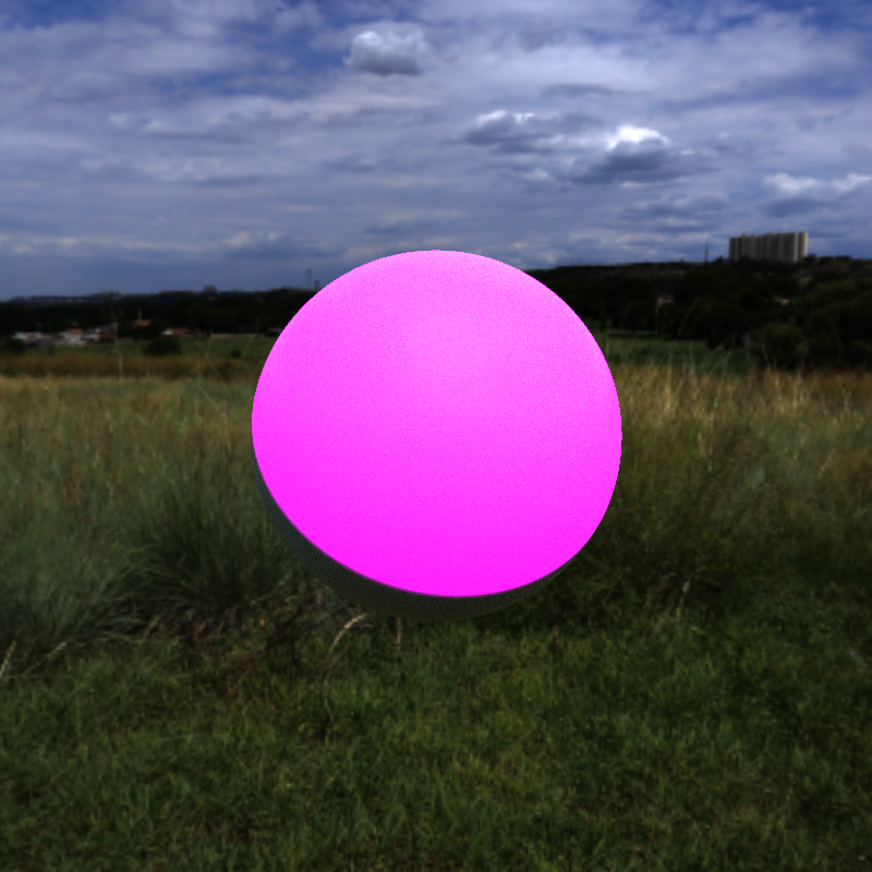
No mapping
Blowout of a colour light
1D LUT
Tone mapping with just a 1D LUT
3D Desaturation LUT
With desaturation LUT
Low Discrepancy Sampling
I implemented sampling using the Sobol (0,2) sequence with a fast gray code technique from the PBRT book. These samples have better distribution in many dimensions and can be used progressively, leading to faster render convergence rates.
Uniform random
9 samples of DOF with uniform random sampling
Low-discrepancy
9 samples of DOF with (0,2) sequence sampling
Blender Export
I put my final scene together in Blender and it took over 15 hours to do, if I had to do it entirely with conversion scripts and lua files it would have been infeasible. So I wrote a script using Blender’s Python API that exports all objects in the scene into OBJ files and a lua file that references them all and sets them up with the right materials.
I can then reference the objects defined in this lua file in my final scene’s lua file, while adding arrangements like portals that Blender can’t do. It also exports object transforms separately so I can do things like replace a cube with a Mandelbox.
I used the same set of film emulation LUTs included in Blender so that I could match Cycles almost exactly.
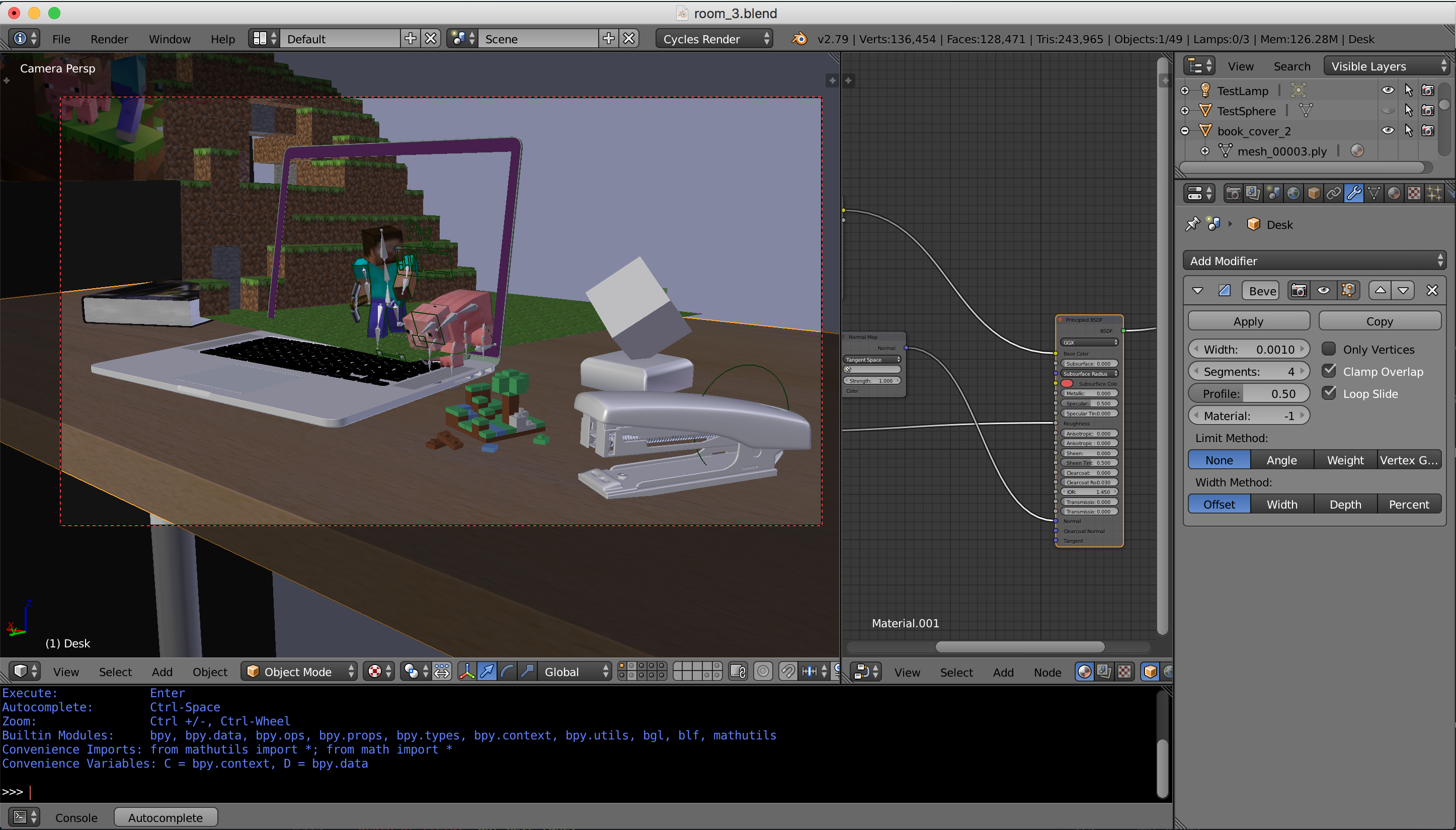
Blender
Final scene in Blender
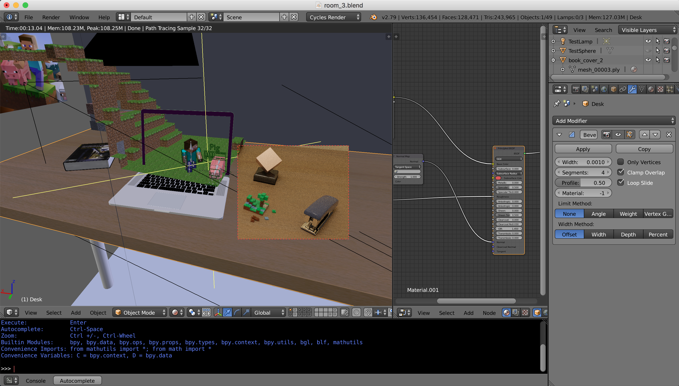
Previewing
Using Cycles to preview parts of the scene
Progressive Rendering
I made my renderer progressive by saving a matrix of Sobol sampler states and running my sampler in epochs of gradually increasing sample count, while keeping the samples for each pixel in each epoch in the innermost loop for cache/branch prediction efficiency. Every epoch it saves an image of its progress so far.
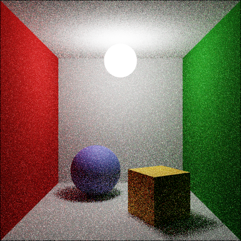
1 sample
1 sample image of a Cornell box
9 samples
9 samples image from same run
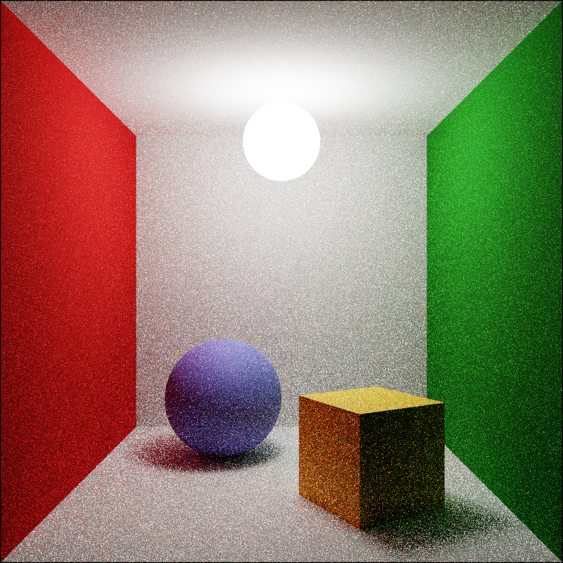
73 samples
73 samples image from same run
10313 samples
10313 samples image from same run
Multithreading & Bar
I made my renderer multithreaded using all available hyperthreads using the C++11 threading library. It distributes rows of image alternately to each thread for evenly distributed difficulty. I implemented a multi-threaded progress bar with proper locking to print nice console progress with ANSI escape codes.
It scales linearly with number of cores. I rendered most images on this page on a 64 core pre-emptible Google Cloud instance for only $0.50 an hour.
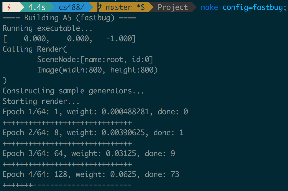
Progress bar
Console output of a render
Misc. Acceleration
I implemented a number of optimizations so that I could render large scenes with path tracing in a reasonable amount of time. I don’t have graphs because these are mostly asymptotic or varying by scene so I could make the graphs show whatever I wanted.
- So that I could render large meshes, I integrated the FastBVH bounding box hierarchy library into my mesh primitive. This took about 2 hours.
- I implemented my own bounding box hierachy checks at the scene node level, although that hierarchy is just the manually constructed hierarchy from Lua.
- I baked the hierarchical transform down into each
GeometryNodeand only apply the transform if it is not the identity, to reduce the number of matrix multiplies per ray per object. - When implementing formulas, I follow best practices for floating point performance and avoid or precompute square roots, trig functions and divisions wherever possible using a number of standard tricks.
- I use the Moller-Trumbore ray-triangle intersection method which is just an algebraic improvement on the one presented in class, but is much faster.
Other Credits
- I learned a lot of what I know from sitting down and reading the PBRT book, many parts of my ray tracer are based on reading the theory and rationale for doing something a certain way in my paper copy of the book while reading it start to finish, and then coding up my own version later. Things built following the methods from PBRT include my path tracing, importance sampling, area light sampling, depth of field and my low-discrepancy sequence generation.
- The primitive signed distance function equations I use for modeling including the box, sphere, ellipsoid and hex bar all come from Inigo Quilez’s SDF modeling page.
- My Mandelbox distance estimator is based on code from a blog post by Mikael Hvidtfeldt Christensen explaining the theory behind the distance estimator. It is nigh-impossible to implement a Mandelbox estimator without referencing code since the way it is designed is based on aesthetics and approximations that don’t always have a perfect theoretical basis.
- All the models and textures in all my scenes except the Mandelbox pedestal and desk were downloaded from the internet, although I re-did the materials myself using the Disney BRDF. The Minecraft hill was sculpted by me in Minecraft and then exported using the jmc2obj tool. Links: Macbook model, stapler model, book model, CGBookCase, CC0Textures, 3DTextures, TextureHaven, HDRIHaven.
- The Lego in my final scene was based on a model found on the Mecabricks Lego CAD site, simplified a bit by me, and then exported.
- The Film emulation LUTs I load in for tone mapping come from Troy Sobotka’s Filmic Blender addon, which was later incorporated directly into Blender. I also had an email conversation with Troy where he clarified some of my understanding of how the different colour spaces fit together.