
Designing and Building a Keyboard: The Body
This summer I set myself the task of designing and building a chording keyboard from scratch. Chording keyboards use a different system of typing where you type entire syllables or words in a single stroke by pressing multiple keys at a time. My keyboard is designed to use a system similar to Velotype. This should theoretically let me type at up to 200WPM.
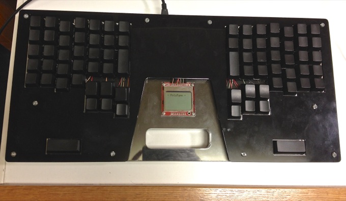
To spoil the ending I managed to build a pretty sweet keyboard that I am using to type this very article. However, I haven’t written the chording software yet so I’m currently using it as a Dvorak keyboard.
Update 10/10/2016: I’ve been using the keyboard for 2 years now. I wrote the chording firmware and tried learning it but after a month I was still typing at 3wpm. But I did end up really liking the keyboard layout used normally so it’s still my primary keyboard. I’ve also upgraded the hardware with cool RGB LEDs. I use the palm keys with a set of Sublime Text shortcuts that is like VIM but the mode is set by the physical state of my palms. This integrates better with the mouse, I never type in the wrong mode, and it’s better for quickly doing something in another mode.
When I started the project I thought it might take 2 weeks to finish the hardware and then I would spend the rest of the summer on software. Boy was I wrong! It took me a month to finish the case and another month of evenings spent soldering after work. I managed to complete the hardware before heading off to Waterloo but only barely.
This post will be mostly about the case and key switches, next I’ll write about the electronics, then the layout (once I design it), and then the software (once I write it).
Overview
The Keys
One thing about chording keyboards is that since you have to press many keys at the same time, it is nice to have very low activation force key switches so that your hands don’t have to work as hard to press more switches.
The Velotype uses custom rubber dome switches with a 15g activation force but those require custom molded silicone sheets and a PCB. Instead I modified Cherry MX Red key switches, which are already some of the lowest force switches out there, and I cut the springs down from 1.5cm to 1.0cm. This gave them an activation force of around 20g instead of 45g.
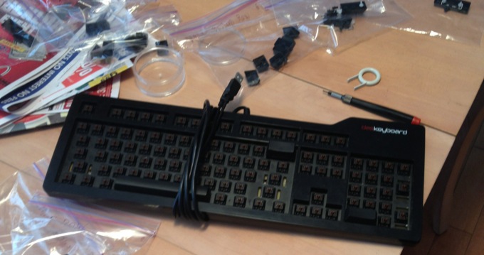
For the key caps I pulled the black blank ones off my Das Keyboard since I figured that buying and shipping a new set of key caps would cost more than the resale value of my (now redundant) Das.
The Case
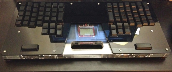
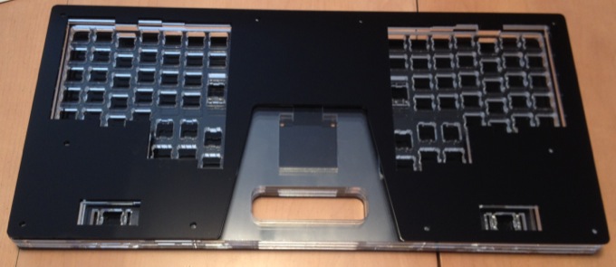
The case was made with layered acrylic sheets cut on the laser cutter at my local library. The layers are bolted together with machine screws with rubber feet at the bottom. The layout is my own design inspired by the Velotype Pro and the Erogdox. The top and bottom layers are thin black acrylic to give the keyboard a nice look and hide the internals. Features include a carrying handle, palm keys and a space for a LCD screen.
The Design
I did all the design in the (free!) student edition of AutoCad. I used cherry switch hole specs posted on the GeekHack forum that I fine tuned by laser cutting small test plates. Before doing the final cut in acrylic I cut one prototype in cheap MDF and also a one-button test keyboard in acrylic. This let me catch a couple design flaws and fine tune my CAD model before the final cut.
My original plan was to draw up the CAD files in two days and then cut them the next day, then spend the next couple days soldering. Turns out I dramatically underestimated the difficulty of designing quality hardware. It took me a week to do the CAD models alone. I had to design the layout, print multiple tests on paper to test ergonomics, then draw up the key cutouts, layout, case and internal pockets in AutoCad. Then I spent days tweaking the kerf, screw placement and PCB pocket size so that everything would fit together well.
The Full Story - Detailed Build Log
The Original Plan (Backstory, skip if you want)
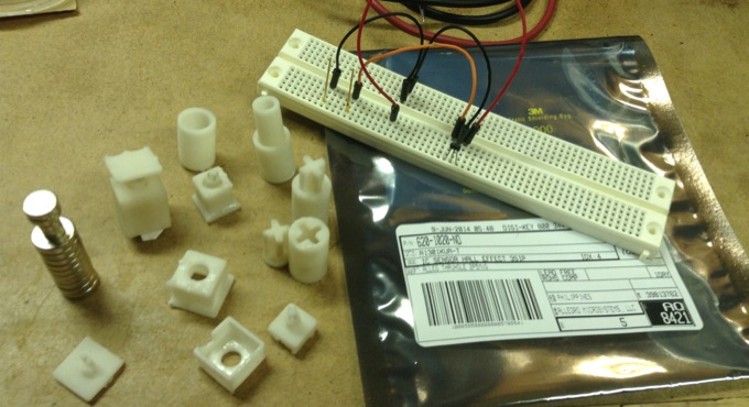
This whole crazy quest started when I got the idea of trying to build a mag-lev hall effect keyboard. The switches would levitate on magnets inside shafts above a hall effect sensor, this would allow very smooth low force switches that gave back analogue signals. This would allow cool things like variable-speed WASD gaming and detection of different typing styles.
I made some crappy prototypes with fridge magnets and paper and it seemed promising so I ordered some hall effect sensors off Digikey and used OpenSCAD to design some 3D models for key switches. I 3D printed them at my library, the first time didn’t turn out well but I tweaked the model and got a decent print. However, the switches didn’t feel very good since smooth shaft sliding requires very tight tolerances that even the very nice SLA 3D printer I was using couldn’t make switches that didn’t wobble and scrape.
I ended up abandoning the project because after further testing I discovered that the magnets in adjacent switches would repel each other causing very weird responses and things like keys being twice as hard to press down when the adjacent one was down. This problem could only be solved by using springs to keep the key up and then switching to weaker magnets, or by shielding each key with something like mu-metal. This is a purely mechanical problem, the hall effect sensors actually weren’t interfered with much by adjacent magnets because they only measure the field strength in one axis.
The Real Quest Begins
After giving up on mag-lev I tried cutting the springs on a cherry brown switch and ended up with a decent low force key switch. Thus started the quest to build a custom chording keyboard. Goals included low force, low cost, ergonomic design, full programmability, and the ability to use it as a normal keyboard.
I started out by doing a bunch of research on other people’s custom keyboards and reading Geekhack threads and blog posts. I used some ideas from the Ergodox, the Atreus, and of course the Velotype Pro.
Drawing up the CAD File
The Layout
I started my layout off by just setting up a massive rectangular grid of keys in AutoCad, I then printed it off at actual size and used my own hand to stagger the columns to match my fingers. One major difference from normal keyboards is that the home row position of the pinky finger is actually on physical row down from the middle, an idea I took from the Velotype. This position is much nicer ergonomically given how short the pinky fingers are, it is just unconventional.
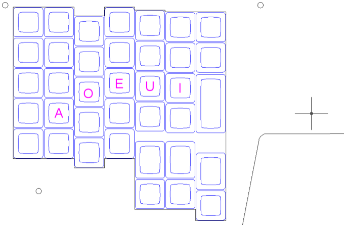
I then used the same print, measure, adjust model, repeat technique to place the thumb cluster and palm keys. The final step was tweaking the layout so that it could use a standard key cap set, this meant doing things like using 1.25U keys for the thumbs instead of 1.5 because there are more of them. While doing this I also kept in mind that each row of key caps has a different profile.
The final step was to mirror the one sided layout to the other side and then measure the natural distance between my hands in order to determine the separation.
The Rest of The Case
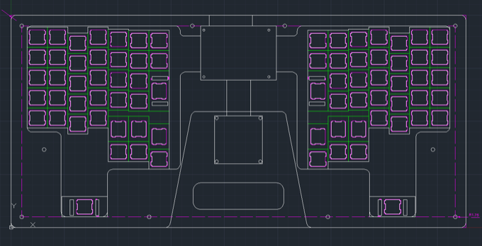
After drawing up the layout I had to design the rest of the case. I drew a box around the outside and then some interior pockets for the wiring. I measured the piece of perfboard and the LCD I had decided on and then put in pockets for those and added channels to the wiring pockets. Then I rounded all the corners to reduce the number of pointy edges as well as the risk of the acrylic cracking.
![]()
Finally I placed the bolt holes in locations that were structurally important and also were solid on all layers. I then measured where the screw holes were on the circuit boards and put those in on the bottom for mounting.
I had drawn the various pockets on different layers in AutoCad so I created a viewport for each physical layer of acrylic and then just set which layers I wanted drawn on each viewport. Bolt holes on all layers, switch holes on the plate layer, etc…
Acquiring Materials
Now that I had my CAD files it was time to acquire the acrylic I needed to cut them in. I called up the Laird Plastics in Ottawa and they had the acrylic I needed but only in $100 4 foot x 8 foot sheets. This was a great price per square foot but it was way more than I needed. So I checked out Canus Plastics and they had the exact acrylic thickness and colours I needed and they even cut me sheets of the size I wanted while I waited. I also went around the back to their dumpster and found some nice off-cuts for practice material.
I got 2 sheets of 43cmx24cm eighth inch black acrylic and 3 sheets of quarter inch 43cmx24cm clear acrylic for $50.
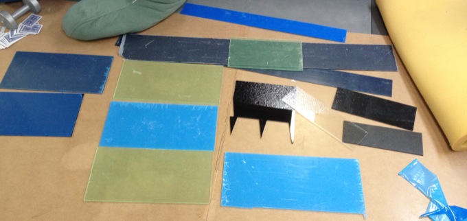
I also went to Home Depot and bought the right size of machine screws as well as some $3 sheets of MDF in the same thicknesses as my acrylic.
Stop, Prototype!
Switch Cutout Kerf
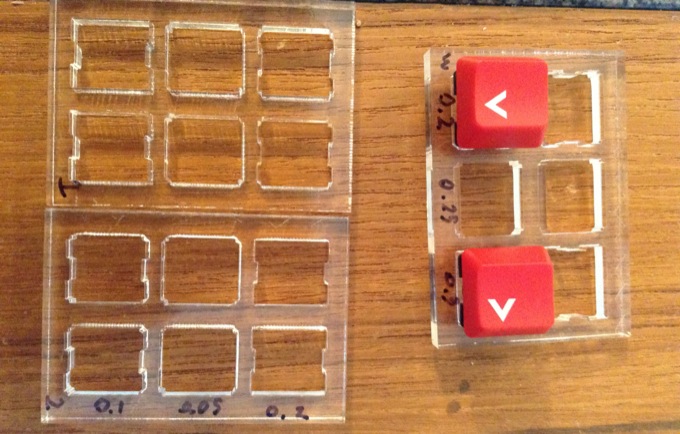
The first thing I wanted to tune was the tightness of my switch cutouts. My acrylic plate was quarter inch thick clear acrylic which is to thick for the switches to snap in so they are friction fit. This meant I had to get the fit very close because I had no PCB to hold the switches in and I didn’t want them popping out if I tried to take off the key caps or turned the keyboard upside down.
I ended up printing 6 different small acrylic test sheets including various insets and resizings of different cherry switch cutout shapes. I measured the results that came off the laser cutter with calipers and found that the laser had 0.2mm kerf in the material I was using.
After adjusting for the kerf I had to figure out how tight I wanted the switch holes. Here are the results of my testing, measured against the Cherry width spec of 19.05mm with calipers:
-0.15mm : Very loose fit, some play, can't pull keycap without pulling out switch.
Keyboard made like this would fall apart easily if it didn't have a PCB.
-0.10mm : Same as -0.15mm maybe imperceptibly tighter
0.00mm : Cherry Spec. Holds switches to be very robust without a PCB. Almost zero play.
Still not tight enough to pull a keycap without pulling out switch.
+0.05mm : Very nice solid fit. Can pull a keycap off without pulling switch.
+0.10mm : Quite tight without stressing switch.
Can easily pull keycap off without feeling switch move.
Takes effort to pop out.
I'm going to use this for my board since it won't have a PCB.
For my final version I decided on the +0.1mm inset (0.3mm including accounting for the laser kerf.).
I also printed some plates to test friction mounting the stabilizers. Turns out you can’t friction mount them and you have to make the slots wider and hot glue them. My CAD models include large stabilizer slots but I didn’t end up installing the stabilizers since they turned out to be unnecessary.
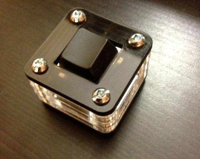
Cute Lil’ Mini Keyboard
To test the acrylic layering, the bolt holes and the border width, and cutting the acrylic I drew up a one key test keyboard that I printed and bolted together. It helped me discover that my bolt holes were too close to the edges for my rubber feet to fit. It also looks super cute. I left a hole for cable so that I can eventually hook it up in case I come up with a good idea for it.
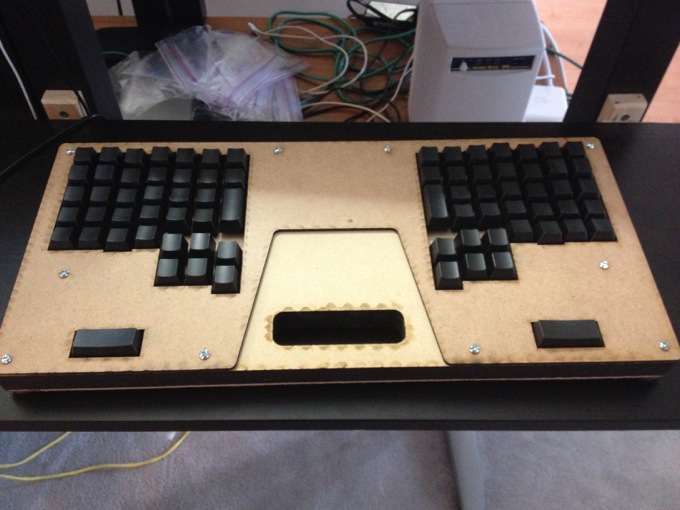
MDF Prototype
So that I didn’t mess up my $50 acrylic sheets I did a test cut in $4 dollars worth of crappy MDF/hardboard and I’m glad I did. This prototype helped me discover that the USB cable didn’t really fit into the case cutout and that I had forgotten to turn some switch cutouts sideways. It also helped me be confident that the final cuts would turn out as I wanted them to.
Modifying Switches
After I cut the MDF prototype I spent 2 one hour sessions in the basement modifying key switches. For each switch I opened it using toothpicks, took out the spring and put it up against a ruler, grabbed it with my wire snippers at the correct point and moved it over a dish and snipped it. Then I put the switch back together and tested the feel. If a switch felt too light I tested it with a multimeter to make sure it didn’t stay down when I pressed it, if it did I tossed it into a rejects pile.
I only modified 46 switches, which was enough for all the keys used in chording, the extra keys which are only used for normal typing and special characters are unmodified. I did all 46 at around 1.5 minutes per switch median time with only 5 rejects (it took significantly longer for some switches because of additional testing).
The source switches were a bag of 110 Cherry MX Reds I bought for $50. I chose Cherry Reds because they work better for low force modification since they don’t have a tactile bump. When I tried modifying Browns sometimes the switch would get stuck on the bump on the way up.
After modifying the switches I mounted them in my MDF prototype with the low force switches in the right places and normal switches everywhere else. Afterwards I put my Das Keyboard key caps on making sure to use the correct rows. I then had a feel-complete version of my keyboard that I could try typing on, it was pretty nice!
Final Cutting
With all my prototyping done I biked to the library with my CAD files and acrylic sheets and spent an hour sitting next to a laser cutter while reading Hacker News and occasionally switching plates and printing a new file and sometimes watching the laser cutter slowly turn a featureless sheet into the keyboard I had been working on for a month.
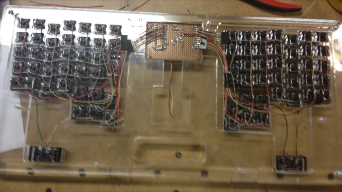
Everything went excellently and I took my sheets home, bolted them together and tested that things fit. I then started transferring switches and keycaps from their respective positions on the MDF prototype to the final acrylic plate.
![]()
One interesting thing I discovered was how susceptible to fingerprints, hair and dust the layered acrylic design is. It doesn’t affect the functionality but it sure looks ugly. When assembling the layers I had to wear rubber gloves and wipe each layer down with a microfiber cloth before bolting them together.
After a while I had a look and feel complete version of my keyboard, now I just had the soldering to do, but that could wait. At this point I was halfway through the summer and I went on vacation from working during my vacation. I took my keyboard shell with me and occasionally practiced typing on the low force switches, just with the keyboard on my lap sitting by a lake with nothing connected to it.
Electronics
For the second month of the summer I worked at Shopify and every day when I got home I worked on designing the electronics and soldering up the key matrix and controller. There’s a lot more to tell about this process but this post is already 2,500 words.
Coming eventually, Part 2 “Designing and Building a Keyboard: The Mind”, in which I will detail the wiring, controller and basic firmware that make bring it to the functional state it is in now.
Update 10/10/2016: Sorry I still haven’t written the other parts. The firmware is on Github though. The electronics is a key matrix connected to a Teensy 3.1 and a MCP23017 multiplexer for more outputs.
Conclusion
With everything included, including prototyping materials, extra backup parts and shipping costs the total price came to $233. This figure does not include the dozens of hours of my own labor I put in.
I posted all the CAD files on Github including the AutoCAD files for the case, the Fritzing file for the controller board and the ruby scripts that generate OpenSCAD scripts that generate mag-lev key models.
For fun, here’s the checked off items of my To-Do list including most of the building and debugging steps (after a certain point when I started th e list). Don’t expect to understand it, it was written for my own reference.
- Design small one switch test layers
- Design PolyType logo plate (didn't turn out well)
- Go to Home Depot and buy 6-32 machine screws&nuts and 2'x2' MDF
- Laser cut switch test layers and logo plate in offcut acrylic
- Design circuit (to size perfboards properly)
- Test stabilizers on small acrylic test plate
- Disassemble Das Keyboard
- Finish full plate designs
- Use correct switch holes on plate design
- Modify 46 red switch springs.
- Add PCB holes to CAD file
- Cut MDF into 3 keyboard plate
- Order diodes, memory, IO expander on digikey
- Fix layout to not use stabilized velo keys
- Laser cut new plate for test cake
- Laser cut finished plate design in MDF
- Test sizing of PCB in MDF
- Mount cherry switches in MDF plate and put das caps on them
- Test feel of entire layout, is last chance to change it.
- USB slot on clear top layer
- turn long thumb key slots sideways
- make display screw holes bigger
- move ring finger column down
- shorter USB slot
- Laser cut finished plate in Acrylic
- Test fit of all plates together
- Test fit of components in pockets
- Mount all switches
- Wire up key matrix rows
- Install stabilizers
- Buy female headers and PCB screws
- Wire up matrix columns
- Solder controller board
- Wire matrix to controller board
Stay tuned for further parts of this saga!
